Jim's
Homemade
|
After spending a few years tinkering with Spud Guns, and more recently BB Machine Guns (BBMGs), I wanted to come up with a way to measure the muzzle velocity of my guns. In addition, after making a BBMG I wanted to be able to measure the Rate Of Fire (ROF). There are instruments available specifically designed for measuring the muzzle velocity of rifles, BB guns etc., for example the ones made by Chrony®, which cost about $80. But half the fun in this stuff is trying to make something useful out of the junk in the garage.
So, I thought I would try to come up with my own shooting chronometer. To do this, I needed a way to detect the projectile, a way to record the event, and a way to analyze the recording. To detect the projectile I have used one or more phototransistors. To record the events I have used the MIC input on my laptop computer. To analyze the recordings I use various share/freeware programs for viewing and manipulating WAV files.
I have used this setup to measure the muzzle velocities of BB guns, spudguns and BB machine guns.
Most PCs and Laptops made in the last ten years came equipped with a sound card. The sound card is essentially an analog to digital (A/D) and digital to analog (D/A) converter. Sound cards are usually dual channel (left and right stereo channels), sample at up to 48,000 (48KHz) samples per second at 8 or 16 bits per sample. CD quality audio is stereo, 48KHz, 16bits. Therefore, the typical sound card is actually a fairly powerful data acquisition system. It is possible to buy better data acquisition systems (i.e., laboratory grade equipment) but they are expensive. For our purposes, the sound card is more than adequate and readily available.
Sound cards may have a couple of different kinds of inputs, including "MIC", line level and system level inputs (for example from the CPU to the sound card). Usually, you don't have direct access to the system level inputs, but you do have access to the MIC and/or line level inputs.
One challenge in using the laptop's sound card to record our signals is figuring out exactly how the MIC input is wired inside the laptop. Apparently, there is no standard definition of what a MIC input is, this goes for both computer sound cards and regular audio components. Typically, the jack is for a 1/8" (3.5mm) stereo plug like this one from RadioShack or this one from one All Electronics. Even though it is called a "stereo" plug it is used in a monaural (single channel) mode here. MIC inputs are generally wired for an Electret microphone which require a power source. Power is provided either by a battery in the microphone itself or by the device it is plugged into. As far as I know the audio signal is always transferred on the tip of the plug and the base of the plug is always the signal ground. If the device supplies power to the microphone the power is placed on either the tip of the plug, or on the plugs ring connector. In the first case, the audio signal from the microphone and the power to the microphone are carried on the same wire.
To figure out what setup your laptop uses you will need to measure the voltage between the tip and ground and the ring and ground of the stereo plug. On my Compaq Presario laptop the tip is at 2.26V (open circuit) and supplies 0.94mA (short circuit). My best guess of how the MIC input is wired inside the Laptop, and how a suitable microphone is wired, is shown below.
Most of what I know about MIC inputs on laptops comes from Tomi Engdahl's page. According to Tomi, SoundBlaster cards put the power on the ring connector, probably something like this;
The other thing you need to know about MIC inputs is that they are "DC uncoupled". If you look at the two circuit diagrams above you'll notice that between the audio input (tip of the jack) and the A/D converter there is a series capacitor. This capacitor blocks any DC in the signal from, for example, the power being supplied to the microphone. This capacitor only passes changes in the input voltage. The capacitor is chosen so that it passes audio range frequencies but blocks slower changes in DC voltage. As a result, if the input voltage changes to a new value and stays there a while (a few tenths of a second) the digitized signal will appear to drift back to zero volts.
In the circuits shown here we will use the power supplied by the MIC input to power our external detector circuits.
Laptops usually don't have line level inputs but most desktop
systems have separate line inputs for the left and right audio
channels. Line level inputs generally expect signals of about +/-1V and
do not supply power. Line level inputs are used between audio
devices other than microphones, for example between a CD player and a
stereo amplifier.
Line inputs have advantages over a MIC input, for example you usually
have access to both the
left and right channels for recording. Since line
level inputs are unpowered, you will
have to supply power to your detector circuit (probably with a 1.5V
battery). Unlike MIC inputs, you don't have to deal with
power
and audio signals being
transferred over the same wire. I don't know if line inputs are
generally DC
uncoupled or not.
To record the MIC signal I used "Sound Recorder" which comes with most Windows computers. In Win98, the Sound Recorder can be started from Start|Programs |Accessories| |Entertainment|Sound Recorder|. If it isn't there, do a "find file" for "SNDREC32.EXE".
Before you do a recording you need to make sure the sound card is actually listening to the MIC input. On Win98, use |Start|Settings|Control Panel| then click on the Multimedia icon. From the Audio tab click in the Recording box click on the big button with a microphone on it and make sure that the Microphone select box is checked. If you have a microphone that works with your computer you can make a test recording to check if everything is set correctly. Start recording a sound with Sound Recorder by clicking on the red record button. Click the stop button (the one with the rectangle), then the play button. If everything is OK you should here your recording played back. If you don't have a microphone, you can just plug in a 1/8" stereo plug while recording and you should get a bunch of static.
By default, Sound Recorder records in PCM (WAV) format at 22,050 Hz with 8 bits per sample in mono. To get the most out of the sound cards digitizing capability, you will want to change the sample rate to 48KHz using |File|Properties| then click the "Convert Now..." button and set the Attributes to "48,000 Hz, 8 Bit, Mono", leave the Format set to "PCM" (same as .WAV). One quirk of Sound Recorder is that every time you create a new recording (|File|New|) it will reset the sample rate back to the default (22,050 Hz) so you have to remember to go through the |File|Properties| process for each new recording.
The second program I use is the demo version of AudioEdit. This demo version cannot save a file, so I only use it for viewing the PCM / WAV files created by Sound Recorder.
The region highlighted in gray was selected with a click-and-drag. The time difference (dT) between these two peaks can be calculated from values on the status bar at the bottom of the window.
dT = (EndPos - StartPos)/(sample rate) = (2376 - 2334)/48000 = 0.875 milliseconds
The resolution at 48KHz sample is 1/48000 = 0.021 milliseconds, about 2.4%, for this pair of peaks.
|
Note Added 16
October 2007. |
Winscope is a free Windows application that uses the PC's sound card to mimic a simple oscilloscope.
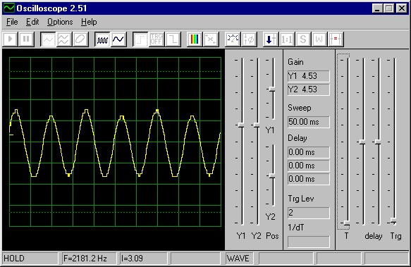
The screen shot above shows the signal you get when you
connect a
phototransistor, like this--
 ,
,
across a Compaq MIC input and point the phototransistor at a 100 watt
light bulb about 10 feet away. (If your MIC input has the microphone
power on the ring instead of the tip, connect the ring and tip with a
1~10K ohm resistor.)
If you look at the WinScope screen shot you will notice that the sweep is set at 50mS, so each horizontal division is 5mS. If you calculate the frequency of the displayed sine wave you get 120Hz, twice the AC frequency in the U.S. The power output of an incandescent light, P=VI, is at twice the AC frequency.
Wav2txt is a Windows program I wrote that converts an audio .wav file (also known as a PCM file) to tab delimited text. This conversion allows you to open a recording as a data file in a spreadsheet program, such as Excel, for analysis and graphing. For more information see my Wav2txt page.
There are several kinds of detectors that could be used for this project. They could be based on light, magnetism (ala a metal detector) and probably several other physical parameters. I choose light since it seemed to be the most straightforward.
There are many types of light detectors, including phototransistors, photo diodes, solar cells and photoresistive cells. Even a standard LED could be used as a photo detector (for example see here, where I think you could get rid of everything except the LED and J-FET!). I choose, for no particularly good reason, to use phototransistors.
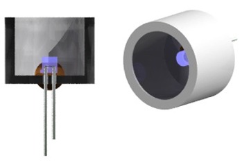
A phototransistor is a regular transistor that has a clear,
instead
of opaque, case. In addition, there is usually no external lead to the
transistors "base" connection.
A phototransistor is essentially a light activated current valve. Brighter light allows greater current to flow from the collector to emitter. Phototransistors are very sensitive to light.
I used Ledtech # LT9593-91-0125 infrared NPN phototransistors (colorless case) from All Electronics (2 for $1.30). According to the data sheet, the response is linear and output current in mA is about equal to the light intensity in mW/cm2. The maximum response is to light at about 850nM (infrared) but it responds pretty well throughout the visible light spectrum. Just about any phototransistor should work OK, for example this one from RadioShack.
 Collector
to Emitter current as a function of incident light for a typical
phototransistor is shown to the right. Full Sun is about 100mW/cm2.
Many phototransistors have
maximum currents of ~30mA, others have response ranges that reach that
of full direct sun.
Collector
to Emitter current as a function of incident light for a typical
phototransistor is shown to the right. Full Sun is about 100mW/cm2.
Many phototransistors have
maximum currents of ~30mA, others have response ranges that reach that
of full direct sun.
In order to maximize the signal from the phototransistors it helps if you restrict the light that reaches it to just that beam of light that the projectile will block. In the drawing below, A shows a phototransistor getting light from all directions. In B, a BB crosses the top of the phototransistor blocking only a small amount of the light. In this case, the change in the signal is relatively small since only a small amount of the total light striking the phototransistor is blocked. To maximize the signal we need to minimize the amount of stray light reaching the phototransistor. We can do this by enclosing the phototransistor in a box (C) with a small hole that allows only a narrow beam of light to reach the phototransistor. Now, we have a narrow beam that can be almost completely blocked by the projectile as in D. Even with a large projectile, like a spud, it helps to limit the amount of light reaching the phototransistor.
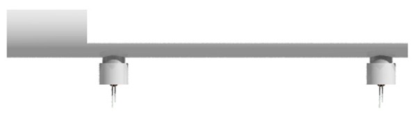
We now need a way to hold two phototransistors, at a fixed separation, parallel to (but not in!) the flight path of our projectile. Since it is critical that the projectile passes directly over the detectors, I've built jigs to attach the detectors directly to the gun barrel.
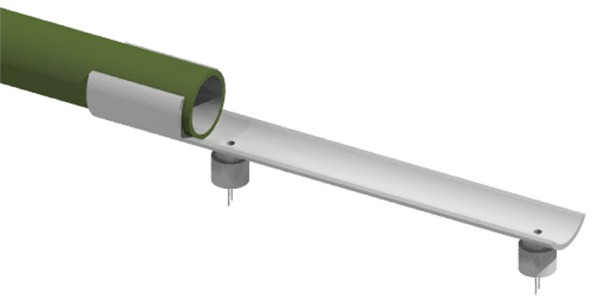
My SpudGun Chrono jig (gray in the picture above) clips onto the muzzle (in green) of a spud gun and holds the two shielded phototransistors at a fixed separation of 12".
Main Jig: To make this jig, start with a 17" length of pipe that matches the spud guns barrel (2"D in this case). Measure 1" in from the end and drill a 3/16" hole. From the same end, measure and drill three more holes, aligned with the first, at 6", 9" and 13" (the holes at 6" and 9" are optional and are not shown in the drawings). These will be the light collimating holes, the first and last holes have a 12" separation between them. The other holes allow for 3", 4", 5", 7" and 8" spacings of the detectors. Now make the two lengthwise cuts as shown below. The dimensions are not critical. I made the clamp portion 3" long and 1-3/8" high, the clamp portion must retain more than half of the pipes circumference. The long skinny region is about 3/8" high.
|
Note Added 16
October 2007. |
This design offsets the jig from the spud path by one pipe wall
thickness (~5/32").
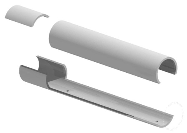
Light Pipes:
Take a piece of
1/2"D pipe, 8" to 12" long, and scribe the arc
of the 2"D pipe near the middle of the pipe. For 2"D pipe you will want
a radius of about 1-3/16". 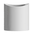 Using
a scroll saw or coping saw cut along the line. You now have two pieces
of 1/2" pipe that should fit perpendicularly to the 2"D pipe
(depending on how good you are with this tricky cut!). To clean up the
cuts, wrap a piece of 100 ~ 150 grit sandpaper around a piece of scrap
2"D pipe and use it to sand your curved cuts. I found it works best if
you sand by moving the 1/2" pipe piece around the 2"D pipe instead of
lengthwise along it. When you are done it should look about like the
image on the right. When you have a reasonably good fit between the
3/4"D pieces and the 2"D pipe you can cut the 1/2"D pieces to their
final length of about 1". Prime and glue the 1/2"D pipe pieces to the
main jig made earlier such that the 1/2" pipe pieces are centered
over the light holes. You will need another pair of light pipes if you
are including the two extra light holes.
Using
a scroll saw or coping saw cut along the line. You now have two pieces
of 1/2" pipe that should fit perpendicularly to the 2"D pipe
(depending on how good you are with this tricky cut!). To clean up the
cuts, wrap a piece of 100 ~ 150 grit sandpaper around a piece of scrap
2"D pipe and use it to sand your curved cuts. I found it works best if
you sand by moving the 1/2" pipe piece around the 2"D pipe instead of
lengthwise along it. When you are done it should look about like the
image on the right. When you have a reasonably good fit between the
3/4"D pieces and the 2"D pipe you can cut the 1/2"D pieces to their
final length of about 1". Prime and glue the 1/2"D pipe pieces to the
main jig made earlier such that the 1/2" pipe pieces are centered
over the light holes. You will need another pair of light pipes if you
are including the two extra light holes.
 PT Carriers: The
carriers for the phototransistors (PT) are made from 1/2" caps.
Drill
two
small holes in the end of each cap large enough for the
phototransistor
leads. Glue the
phototransitrs into the inside of the caps, passing the
leads through the small holes.
I put a big glob of "Liquid Nails" (the brownish blob in the picture)
inside the cap and then pushed the
phototransistor down into it. Glue around the outside of the
phototransistor is not a problem since we really want the light to only
enter
the
top of the phototransistor anyway. For Ledtech phototransistors, the
long lead is
the
emitter and the short lead is the collector.
PT Carriers: The
carriers for the phototransistors (PT) are made from 1/2" caps.
Drill
two
small holes in the end of each cap large enough for the
phototransistor
leads. Glue the
phototransitrs into the inside of the caps, passing the
leads through the small holes.
I put a big glob of "Liquid Nails" (the brownish blob in the picture)
inside the cap and then pushed the
phototransistor down into it. Glue around the outside of the
phototransistor is not a problem since we really want the light to only
enter
the
top of the phototransistor anyway. For Ledtech phototransistors, the
long lead is
the
emitter and the short lead is the collector.
Finishing: PVC is not very opaque, so I painted the jig flat black, including the insides of the 3/4"D pipes, but not the insides of the 3/4" caps where the phototransistors are glued. It is also a good idea to mask the bottom half inch or so of the outside of the light pipes when painting so they don't get painted (but the inside does).
The caps with the phototransistors are not glued in place, instead they are just slipped on. This allows you to move the detectors to other jigs. You don't want to paint the end of the light pipes so that it is easier to get these caps on and off.
Some more views --
The final step is to attach wire to the phototransistors, preferably by soldering. Make sure you insulate the wires with heat shrink tubing or electrical tape to keep them from shorting together. It is also a good idea to label the collector and emitter wires so you can keep track of which are which.
The two phototransistors are just wired in series like this --
 |
Detectors
just pointed
horizontally out the garage door on a bright
sunny day. Voltages:
|
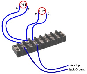
And, too keep from accidentally pulling the laptop off the table, I wired things up using a bus strip clamped to the table, like this --
To use the SpudGun chrono jig, just clip the jig on the barrel of your gun, hook up the wires, point the light holes towards bright sky, start the recorder and fire.
|
Note Added 12 Sept.
2005. |
We tested this setup on a moderately sized propane fired gun spudgun. The chamber is 3"Dx11"L chamber with a 2"Dx30"L barrel, a double bevel muzzle knife, chamber fan, and piezo ignitor. We measure fuel with a syringe. The fueling system and pics of the gun are here.
We have only chrono'd this gun a few times, the average muzzle velocity, with half a potato, is 340fps.
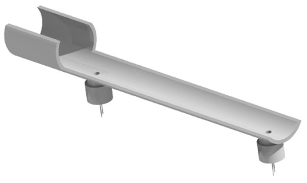
The jig I built for a BB machine gun (BBMG) is shown below. The BBMGs barrel shroud is green, the barrel itself copper colored, and the chrono jig light blue and gray.
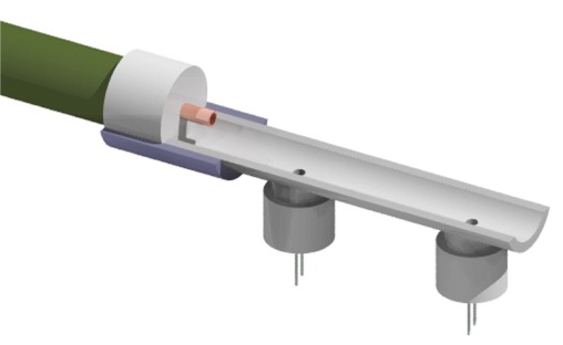
The chrono jig for the BBMG is a little different than for a spud gun since we need to hold the detectors aligned with the 1/4" barrel and not just the 3/4" barrel shroud. And, since a BB is much smaller than a spud, the alignment of the flight path with the detectors is more critical.
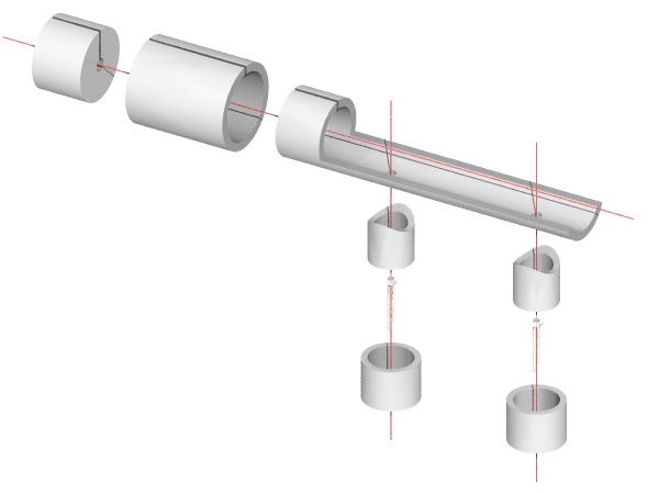
My jig was constructed from (left to right in the diagram below) a 3/4" cap with a 1/4"D hole for the BBMG barrel, a slice out of a 1" coupler (in blue), and a slice of 1" pipe (about 6" long). The light pipes and phototransistor carriers are from 1/2" pipe and are the same as for the spudgun chrono jig. I sliced the cap nearly in half (not shown in the picture, see the example in the second design) to make it easier to slip the jig on and off the BBMG barrel shroud.
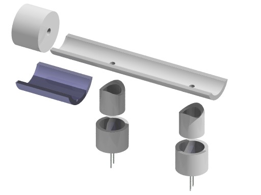
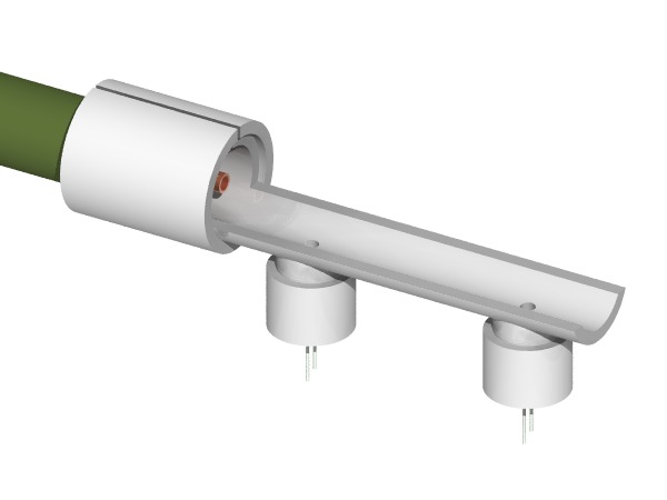
A revised design is shown in the two drawings below. I haven't actually made this design.
An exploded view of this design is shown below. Notice the lengthwise slices in the cap, coupler, and portion of the the 1" pipe. These slices help correct for small differences in the ID/OD of the various pieces; 3/4" cap, 1" coupler, and 1" pipe. The phototransistors are kind of hard to see.
For the BBMG I wanted to be able to measure both the muzzle velocity and the rate of fire (ROF). Since this is a machine gun, there are multiple projectiles in flight at the same time, hence there is a possibility of having more than one projectile in the speed trap at the same time. For certain combinations of muzzle velocity, ROF and detector separation, it may get confusing as to which pairs of peaks represent the same BB.
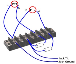
To address this issue, I changed the circuit so that the two PTs give different signals. Instead of wiring the PTs in series, they are wired in parallel and each has a different series resistor (see the schematic below). Since the resistors are different, the two detectors will give different peak amplitudes when they are blocked by a BB. In this case, blocking PT1 will give a bigger peak than blocking PT2. In addition, this circuit gives four distinct signals; AonBon, AonBoff, AoffBon, AoffBoff, whereas the series circuit nominally gives two distinct signals; AonBon, AonBoff = AoffBon = AoffBoff. The drawback of the parallel circuit with resistors is that it requires a much brighter light source than the series circuit without resistors.
|
 |
My BBMG is very similar to designs published on the web. I believe the first published design of this type was by 'spudsonfire', and posted in the forums at www.spudtech.com. I used a 3 foot length of 1/4" OD (3/16" ID) stainless steel tubing for the barrel. For detailed descriptions of BBMGs see Burnt Latke's or advancedspud's excellent pages.
For the BBMG I wanted to be able to measure both the muzzle velocity and the rate of fire (ROF). Since this is a machine gun, there are multiple projectiles in flight at the same time, hence there is a possibility of having more than one projectile in the speed trap at the same time. For certain combinations of muzzle velocity, ROF and detector separation, it may get confusing as to which pairs of peaks represent the same BB.
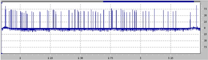
The "recordings" were made with a 3" separation of the gates, on a bright sunlit day with the detectors more or less pointing into the sun. The compressor's outlet regulator was maxed out at "120PSI". The Audio gain for the recording was 25% of full scale and the laptop was running on battery power. (The AC adapter gives a pretty noisy baseline in the recordings.)
A typical recording is shown below, two short burst and a long one --
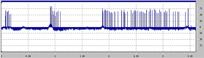
Zooming in on the long burst (about 1.5 seconds), is shown below. At this zoom level each BB still looks like a single peak, instead of a pair of peaks, --
Zooming in some more, to just the first eight BB's of the long burst, we can see the pair of peaks for each BB --
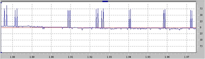
In the graph above it is pretty obvious that the muzzle velocity (the distance between the peaks in a pair) is fairly consistent from BB to BB, but the ROF (the distance between the sets of peaks) is highly variable. For example, the time between the first and second BB is about 5mS (equivalent to a ROF=200rps) compared to 27mS (ROF=37rps) for the second and third BBs.
For each of the three burst we can calculate the ROF from
ROF = (Number BBs -1) / (time last BB - time first BB)
| Burst |
Number of BBs |
Time |
ROF |
| 1 |
6 |
0.101 |
59 |
| 2 |
11 |
0.185 |
59 |
| 3 |
58 |
1.53 |
38 |
| Average |
52 |
||
| Std Dev |
12 | ||
The two short bursts had the same ROF, but I suspect that is just luck. The long burst had a much lower ROF than the short bursts.
To help extract all of the time values for the long burst, the audio wav file was converted into a tab delimited text file with wav2txt. The text file was loaded into Excel and the various values were calculated. The muzzle velocity and the "instantaneous" rate of fire (iROF) were calculated with;
| Muzzle Velocity | = | 0.25' / (Time2-Time1) | (gate separation = 3" = 0.25') |
| iROF | = | 1 / (Time1bb(i+1) - Time1bb(i)) | |
The results for each BB of the long burst are shown below.
| BB # | Time1 (sec) | Time2 (sec) | dT (sec) | Muzzle Velocity (fps) | iROF (rps) |
| 1 | 1.876250 | 1.877396 | 0.00115 | 218.2 | -- |
| 2 | 1.881708 | 1.882688 | 0.00098 | 255.3 | 183.2 |
| 3 | 1.908833 | 1.909792 | 0.00096 | 260.9 | 36.9 |
| 4 | 1.923250 | 1.924146 | 0.00090 | 279.1 | 69.4 |
| 5 | 1.926063 | 1.926958 | 0.00090 | 279.1 | 355.6 |
| 6 | 1.940125 | 1.940813 | 0.00069 | 363.6 | 71.1 |
| 7 | 1.957792 | 1.958479 | 0.00069 | 363.6 | 56.6 |
| 8 | 1.971667 | 1.972333 | 0.00067 | 375.0 | 72.1 |
| 9 | 2.003250 | 2.004042 | 0.00079 | 315.8 | 31.7 |
| 10 | 2.014750 | 2.015438 | 0.00069 | 363.6 | 87.0 |
| 11 | 2.030688 | 2.031375 | 0.00069 | 363.6 | 62.7 |
| 12 | 2.046208 | 2.046979 | 0.00077 | 324.3 | 64.4 |
| 13 | 2.056708 | 2.057375 | 0.00067 | 375.0 | 95.2 |
| 14 | 2.096375 | 2.097125 | 0.00075 | 333.3 | 25.2 |
| 15 | 2.109188 | 2.109875 | 0.00069 | 363.6 | 78.0 |
| 16 | 2.163875 | 2.164583 | 0.00071 | 352.9 | 18.3 |
| 17 | 2.224958 | 2.225833 | 0.00087 | 285.7 | 16.4 |
| 18 | 2.236958 | 2.237688 | 0.00073 | 342.9 | 83.3 |
| 19 | 2.272729 | 2.273667 | 0.00094 | 266.7 | 28.0 |
| 20 | 2.280521 | 2.281313 | 0.00079 | 315.8 | 128.3 |
| 21 | 2.295229 | 2.295958 | 0.00073 | 342.9 | 68.0 |
| 22 | 2.338958 | 2.339667 | 0.00071 | 352.9 | 22.9 |
| 23 | 2.404792 | 2.405521 | 0.00073 | 342.9 | 15.2 |
| 24 | 2.430271 | 2.431000 | 0.00073 | 342.9 | 39.2 |
| 25 | 2.453479 | 2.454188 | 0.00071 | 352.9 | 43.1 |
| 26 | 2.477125 | 2.478042 | 0.00092 | 272.7 | 42.3 |
| 27 | 2.485083 | 2.485792 | 0.00071 | 352.9 | 125.7 |
| 28 | 2.501271 | 2.501958 | 0.00069 | 363.6 | 61.8 |
| 29 | 2.529375 | 2.530063 | 0.00069 | 363.6 | 35.6 |
| 30 | 2.563875 | 2.564563 | 0.00069 | 363.6 | 29.0 |
| 31 | 2.588604 | 2.589333 | 0.00073 | 342.9 | 40.4 |
| 32 | 2.603354 | 2.604042 | 0.00069 | 363.6 | 67.8 |
| 33 | 2.625125 | 2.625813 | 0.00069 | 363.6 | 45.9 |
| 34 | 2.644563 | 2.645250 | 0.00069 | 363.6 | 51.4 |
| 35 | 2.666458 | 2.667146 | 0.00069 | 363.6 | 45.7 |
| 36 | 2.690646 | 2.691458 | 0.00081 | 307.7 | 41.3 |
| 37 | 2.693583 | 2.694396 | 0.00081 | 307.7 | 340.4 |
| 38 | 2.737813 | 2.738500 | 0.00069 | 363.6 | 22.6 |
| 39 | 2.756625 | 2.757563 | 0.00094 | 266.7 | 53.2 |
| 40 | 2.763208 | 2.763917 | 0.00071 | 352.9 | 151.9 |
| 41 | 2.796917 | 2.797583 | 0.00067 | 375.0 | 29.7 |
| 42 | 2.835292 | 2.836125 | 0.00083 | 300.0 | 26.1 |
| 43 | 2.846333 | 2.847042 | 0.00071 | 352.9 | 90.6 |
| 44 | 2.861792 | 2.862479 | 0.00069 | 363.6 | 64.7 |
| 45 | 2.883333 | 2.884021 | 0.00069 | 363.6 | 46.4 |
| 46 | 2.909604 | 2.910271 | 0.00067 | 375.0 | 38.1 |
| 47 | 2.932125 | 2.932813 | 0.00069 | 363.6 | 44.4 |
| 48 | 2.948667 | 2.949396 | 0.00073 | 342.9 | 60.5 |
| 49 | 2.961750 | 2.962438 | 0.00069 | 363.6 | 76.4 |
| 50 | 3.018438 | 3.019167 | 0.00073 | 342.9 | 17.6 |
| 51 | 3.041333 | 3.042042 | 0.00071 | 352.9 | 43.7 |
| 52 | 3.067188 | 3.067875 | 0.00069 | 363.6 | 38.7 |
| 53 | 3.112604 | 3.113333 | 0.00073 | 342.9 | 22.0 |
| 54 | 3.188438 | 3.189188 | 0.00075 | 333.3 | 13.2 |
| 55 | 3.225458 | 3.226208 | 0.00075 | 333.3 | 27.0 |
| 56 | 3.268375 | 3.269104 | 0.00073 | 342.9 | 23.3 |
| 57 | 3.290021 | 3.290729 | 0.00071 | 352.9 | 46.2 |
| 58 | 3.410125 | 3.410896 | 0.00077 | 324.3 | 8.3 |
| 59 | 3.462396 | 3.463521 | 0.00113 | 222.2 | 19.1 |
| Average = | 335 | 63 | |||
| Std Dev = | 39 | 64 | |||
|
Minimum
=
|
218 | 8 | |||
| Maximum = | 375 | 356 | |||
This long burst fired 58 BB's in 1.53 seconds at an average muzzle velocity of 335 +/- 39 fps. To get calibrated, a low to moderate powered BB gun fires in the 300 - 400 fps, a high powered BB gun at perhaps 600 fps.
The ROF for this burst was 38 rps (2310 rpm) based on the time and number of BB's, but the "instantaneous" average ROF was 63 rps (3780 rpm) +/- 64 rpm. Clearly, the ROF is highly variable, probably due to the randomness of BBs actually making it into the barrel.
For comparison, muzzle velocities and ROFs of various guns are shown below.
| Weapon |
Muzzle
Velocity (fps) |
max
ROF
(rpm) |
| RED RYDER® BB Gun
(Crossman) |
270 |
single
shot |
| DY880 Multi-Pump BB
Gun (Daisy) |
750 |
single shot |
| BBMG |
335 |
2275 |
| Tokyo Marui EG700
(AirSoft) |
280 |
750 |
| M-16 assault rifle (older
full auto models) |
2,800 |
800 |
| M-60 heavy machine
gun |
2,800 |
550 |
| M-134 Minigun (modern
gattling machine gun) |
2,800 |
2,000
&
4,000 |
My BBMG has about he same muzzle velocity as a typical low/moderate powered BB gun. The ROF, though only about 1/3 what most people have "guestimated" the ROF of this type of BBMG, is still well above the ROF of real machine guns and is approaching the ROF of the fastest military machine gun -- the Minigun. All in all, not bad for hunk of tubing, some PVC and a compressor. It is possible that changes in my BBMG could significantly affect performance. In particular, small changes in the the height of the shroud would probably change the ROF significantly.
All in all, the detector works pretty well for this application. It appears though that the parallel design with resistors is a bit overkill. I suspect that the simpler "two detectors in series" (no resistors) circuit would work just as well, and is more light sensitive. Since the series design is more sensitive, the alignment of the detectors with the sun is less important and pretty much any patch of bright sky will do.
The accuracy of this setup is OK. With a 48KHz sample rate and detectors separated by 3 inches, the accuracy at a 300fps muzzle velocity should be about +/-8 fps. If the muzzle velocity is significantly higher then it would probably be a good idea to increase the gate separation. Though at longer gate separation you have to worry about having two BB's in the trap at the same time which might make figuring out which pairs of peaks represent the same BB difficult.
We have also measured the muzzle velocity of a Daisy "Grizzly" BB gun. This is a low end, single pump BB gun with a muzzle velocity, according to Daisy, of 320 fps. We thought we would see if additional pumps increased the muzzle velocity.
We used the Spud Gun chrono jig, using the 3 inch separation gates, and simply clamped the jig to the barrel. Alignment of the barrel to the jig is critical since the BB is so small. To insure correct alignment we inserted a 3/16" piece of dowel into the barrel to "bore sight" the alignment with the jig. We moved the jig about until the shadow of the stick crossed the two detector holes.
The circuit was the same as described for the SpudGun, just two photodetectors in series.
Below is a typical recording, displayed in AudioEdit, of a BB
fired
from the Grizzly.
From the graph above, the peak to peak separation is 875uS, therefore, the muzzle velocity is 3"/12"/875uS = 286fps.
The results for the "pumps vs. muzzle velocity" study are shown below. The minimum sampling error is +/- 1 sample point which is ~8FPS.
| Shot # | # Pumps | dTime (sec) | FPS | ||
| 1 | 1 | 0.000854 | 292.7 | ||
| 2 | 1 | 0.000917 | 272.7 | ||
| 3 | 1 | 0.000979 | 255.3 | ||
| 4 | 1 | 0.000896 | 279.1 | Avg = | 277 |
| 5 | 1 | 0.000875 | 285.7 | SD = | 14 |
| 6 | 2 | 0.000833 | 300.0 | ||
| 7 | 2 | 0.000792 | 315.8 | ||
| 8 | 2 | 0.000813 | 307.7 | ||
| 9 | 2 | 0.000813 | 307.7 | Avg = | 309 |
| 10 | 2 | 0.000792 | 315.8 | SD = | 7 |
| 11 | 3 | 0.000833 | 300.0 | ||
| 12 | 3 | 0.000875 | 285.7 | ||
| 13 | 3 | 0.000750 | 333.3 | ||
| 14 | 3 | 0.000813 | 307.7 | Avg = | 309 |
| 15 | 3 | 0.000792 | 315.8 | SD = | 18 |
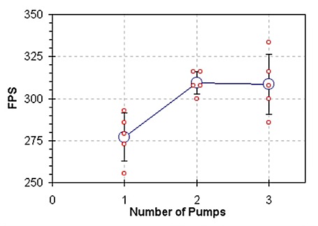
It appears as if there is an increase in muzzle velocity with two versus one pump, with two pumps boosting the muzzle velocity by about 30fps (10%). An additional pump does not appear to increase the muzzle velocity.
This is what you get if you point a TV infrared remote control into one of the detectors --
and this is what it sounds like. (If you have two detectors wired in series, then the other detector needs to be pointed at a bright light.)
The actual jigs looks OK, but not nearly as nice as the POV-Ray images. And I'm not even all the good with POV-Ray. POV-Ray is a great freeware package for doing ray-traced images. The learning curve is pretty steep, but once you get the hang of it, you can make amazing images. This is my favorite.
It is important that all of the electrical connections are secure, otherwise you get a lot of static in your recordings, especially when the gun's recoil shakes everything.
This setup does not work well with 120V AC light sources since they blink on and off 120 times per second. Sunlight or a battery powered light source work best.
You could construct a jig with its own light sources, such as a pair of infrared LEDs.
My Compaq laptop gives much better recordings when the AC power supply is unplugged.
The minimum "event width" for a sound card running at 48KHz is 21 microseconds. In practice you probably want the "events" to last at least twice that, or ~40 microseconds. An "event" would be a single BB passing a single detector.
The overall accuracy of the chrono depends on the sampling rate of the sound card, distance between the two detectors and the muzzle velocity. You probably want at least 20 data points between the two detectors which gives a timing error of <5% (1 in 20).
When using series resistors with the PTs you limit the maximum current that the PT can transfer. The graph "A" below shows a typical PT's output curve. If an 8.2K resistor is included in the circuit, then the output curve is as shown in "B" (assuming 2.25V). The curve in "B" is OK as long as the current resulting from the "light" and "dark" light levels are not the same. For example, the pair of light levels marked "a" and "c" are OK, but "c" and "d" are not.
| A. |
B. |
Other ways of recording a signal with a PC which I considered, include;
Would the setup outlined on this page work with a rifle? Assume a 1/2" long projectile, 2000 fps muzzle velocity, 3/16" light holes and 12" separation between detectors --
Peak Width = (0.5" +
0.1875") / 12 / 2000fps = 29uS, equivalent to 1.4 samples at 48KHz
Peak-1 to Peak-2 time = 1' / 2000 = 500uS, equivalent to 24 samples at
48KHz
It looks like it would be marginal. The peaks may be too narrow at just 1.4 samples wide. The accuracy wouldn't be too bad, about 4% error.
Better results might be possible by using light holes elongated to slots of about 1" length and increasing the detector separation to 2'. This would give --
Peak Width = (0.5" + 1") / 12 /2000fps =
62uS (3 samples at 48KHz)
Peak-1 to Peak-2 time = 2' / 2000 = 1000uS (48 samples at 48KHz)
This might be adequate, accuracy would be about 2%.
Send me an email
Modified:
16
October 2007
©2007 James Sluka